Embedded Computers

Readout Thread
Transfer Thread

ORCA uses crate-level embedded single board computers (SBC) as a direct extension of itself. Download code and makefiles are managed as part of ORCA’s code base and are transferred to the SBC and compiled in a semi-automatic fashion.
The code that is downloaded to the SBC is composed of a small set of routines that handle the communication socket, the data transfer circular buffer, and other common functions. Specific code for a given SBC is combined with the base code as needed for different types of hardware, i.e. VME, cPCI, etc.

Core code for socket handling, data transfer, common functionality.

VME
HW specific makefile, code for event readout, and HW access.

cPCI
HW specific makefile, code for event readout, and HW access.

Code for specific HW
IPE
HW specific makefile, code for event readout, and HW access.


Orca assembles the custom code package for a specific SBC, downloads, compiles, starts, and initiates a connection
Since each code set has its own makefile, the package can be linked to specific HW drivers and/or libraries
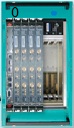
SBC running Linux
Internet connection
typedef struct {
uint32_t header;
uint32_t total_cards; // total sum of all cards
struct { // structure required for card
uint32_t hw_type_id; // unique hardware identifier code
uint32_t hw_mask[10]; // hardware identifier mask to OR into data word
uint32_t slot; // slot identifier
uint32_t crate; // crate identifier
uint32_t base_add; // base addresses for each card
uint32_t add_mod; // address modifier (if needed)
uint32_t deviceSpecificData[256]; // a card can use this block as needed.
uint32_t next_Card_Index; // next card_info index to be read after this one.
uint32_t num_Trigger_Indexes; // number of triggers for this card
uint32_t next_Trigger_Index[3]; //card_info index for device specific trigger
} card_info[MAX_CARDS];
} SBC_crate_config;


Circular Buffer
Internet
connection

Data Records


Readout
Loop


Starting the Crate
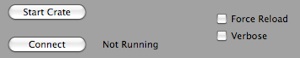
When a SBC Start Crate is initiated from an SBC control dialog, ORCA does the following actions.
If the Force Reload option is selected:
-
1. All code in the ORCA folder in the SBC is deleted.
-
2. The startup scripts are modified as necessary.
-
3. The core code is downloaded.
-
4. The HW specific code is downloaded.
-
5. A organization script is run to make a flat ORCA folder on the SBC.
-
6. A compile script is run on the SBC.
-
7. The code is started.
-
8. The socket is opened.
Part of the SBC control dialog
If the Force Reload option is not selected:
-
1. A connection is attempted.
-
2.If the connection is successful, then we’re done.
-
3.If a connection can not be made, then an attempt is made to start the code.
-
4.If a connection can still not be made, then a complete reload of the code is done as if the Force Reload option had been selected.
Code Organization
The SBC code takes data using two threads, a readout thread and a data transfer thread. The data transfer thread also handles all communication to/from ORCA
Data Structures
The SBC_crate_config data structure is used to pass the hardware readout list to the SBC. It contains all information needed for the SBC to set up data records, determine base addresses, etc.
The actual definition looks like this:
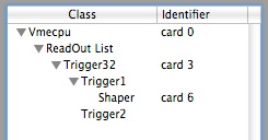
If the readout list is flat then the structure is also flat and the fields, num_Trigger_Indexes will be set to zero. If, however, a piece of hardware is a trigger card that controls the readout based on some trigger information then the num_Trigger_Indexes will be non-zero and the next_Trigger_Index[0] will indicate the offset to the next to card to be read in the case of a trigger.
The configuration structure is set up automatically based on the readout list in the ORCA Data Taker. The only data that each object needs to fill in are the dataIDs, slot, crate, base address, and any device specific information.
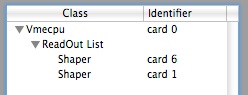
Flat Readout
Triggered Readout

Hardware Specific Readout
In the HW_Readout.c file of the hardware specific part of the SBC code the readout of the hardware is controlled by the readHW routine:
int32_t readHW(SBC_crate_config* config,int32_t index, SBC_LAM_Data* lamData)
{
if(index<config->total_cards && index>=0) {
switch(config->card_info[index].hw_type_id){
case kShaper: index = Readout_Shaper(config,index,lamData); break;
case kGretina: index = Readout_Gretina(config,index,lamData); break;
case kTrigger32: index = Readout_TR32_Data(config,index,lamData); break;
case kCaen: index = Readout_CAEN(config,index,lamData); break;
...
...
...
default: index = -1; break;
}
return index;
}
else return -1;
}

Each object to be read out must have a unique id, which is set in xxx_HW_Definitions.h


Each object must define a readout routine

int32_t Readout_Shaper(SBC_crate_config* config,int32_t index, SBC_LAM_Data* lamData)
{
uint32_t baseAddress = config->card_info[index].base_add;
uint32_t conversionRegOffset = config->card_info[index].deviceSpecificData[1];
char theConversionMask;
int32_t result = read_device(vmeAM29Handle,&theConversionMask,1,baseAddress+conversionRegOffset);
if(result == 1 && theConversionMask != 0){
uint32_t dataId = config->card_info[index].hw_mask[0];
uint32_t slot = config->card_info[index].slot;
uint32_t crate = config->card_info[index].crate;
uint32_t locationMask = ((crate & 0x01e)<<21) | ((slot & 0x0000001f)<<16);
uint32_t onlineMask = config->card_info[index].deviceSpecificData[0];
uint32_t firstAdcRegOffset = config->card_info[index].deviceSpecificData[2];
int16_t channel;
for (channel=0; channel<8; ++channel) {
if(onlineMask & theConversionMask & (1L<<channel)){
uint16_t aValue;
result = read_device(vmeAM29Handle,(char*)&aValue,
2,baseAddress+firstAdcRegOffset+2*channel);
if(result == 2){
if(((dataId) & 0x80000000)){ //short form
data[dataIndex++] = dataId |
locationMask |
((channel & 0x0000000f) << 12) |
(aValue & 0x0fff);
}
else { //long form
data[dataIndex++] = dataId | 2;
data[dataIndex++] = locationMask | ((channel & 0x0000000f) << 12) | (aValue & 0x0fff);
}
}
else if (result < 0)LogBusError("Rd Err: Shaper 0x%04x %s",baseAddress,strerror(errno));
}
}
}
else if (result < 0)LogBusError("Rd Err: Shaper 0x%04x %s",baseAddress,strerror(errno));
return config->card_info[index].next_Card_Index;
}
Each read out routine then uses calls to the local SBC hardware driver to determine if an event needs to be read out and then assembles that event into a data structure that ORCA expects. As an example, here is the read out routine for the VME CENPA shaper card:
The dataID and other device specific info is in the config structure
Use the device driver to determine if an event is ready to be read out
The data record needs to be the ORCA specified format
Always return the next_Card_Index
If this card was to read out children based on a trigger, you’d make a call back to readHW() with the child’s index.
Note that the data is just put into the array data[] and the dataIndex is incremented as needed. The actual shipping of the data record into the circular buffer is done automatically.
Sharing the network between the Mac and the SBC
These instructions describe how to share a network connection between a Mac equipped with dual ethernet ports and a Single Board Computer (SBC) running Crux version 2.4. It is assumed that the Ethernet 1 port on the Mac is already configured for use on a local network. The SBC should be connected to the Mac's Ethernet 2 port (note that it is not necessary to use an Ethernet crossover cable to connect the Mac to another Ethernet device).
From the apple menu select System Preferences -> Network.
Select Ethernet 2 and in the Configure: field choose Manually from the drop down menu.
Modify the following fields.
IP Address: $$$.$$$.$$$.$$$ this will be the gateway address for the SBC (e.g. 10.0.0.1)
Subnet Mask: 255.255.255.0
Router: $$$.$$$.$$$.$$$
The remaining fields should remain blank.
Now open System Preferences -> Sharing. In the Internet Sharing pane choose to share your connection from Ethernet 1 to computers using Ethernet 2. Turn on Internet Sharing by clicking the check box next to Internet Sharing. A green dot will appear alerting you that Internet Sharing is enabled.
Log in to the SBC as root.
Modify /etc/rc.d/net. Change the lines that look like:
...
/sbin/ip addr add ###.###.##.###/24 dev eth0 broadcast +
...
/sbin/ip route add default via $$$.$$$.$$$.$$$
...
/sbin/ip addr del ###.###.###.###/24 dev eth0
replacing ###.###.###.### with the desired SBC IP address and replacing $$$.$$$.$$$.$$$ with the IP address assigned to the Ethernet 2 port on the Mac.
Restart the network service by typing
/etc/rc.d/net restart