CAEN V1190

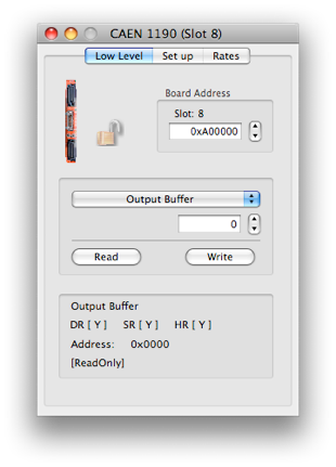

Set the VME Address

See manual for more details

The module programming is performed via a microcontroller that implements a high-level user friendly interface. The VME interface allows the module to work in A24 and A32 addressing modes. The board houses a 32 k x 32 bit deep Output Buffer, that can be readout via VME in a completely independent way from the acquisition itself. The internal registers are available in D16 mode only, while the Output Buffer is accessible in D32, BLT32 or MBLT64. The module supports also the Chained Block Transfer mechanism and the Multicast commands.
Please refer to the manual for more details.
V1190 Data Record format
//-------------------------------------------------------------------------------
data format
0000 0000 0000 0000 0000 0000 0000 0000
^^^^ ^^^^ ^^^^ ^^---------------------- device type
^^ ^^^^ ^^^^ ^^^^ ^^^^ length of record including this header
0000 0000 0000 0000 0000 0000 0000 0000
^^^^ ^--------------------------------- spare
^^------------------------------- spare
^ ^^^-------------------------- crate
^ ^^^^-------------------- card
// n bytes of raw data follow.
// each word following can be decoded by looking at the top 5 bits
0100 0000 0000 0000 0000 0000 0000 0000 Global Header
^^^^ ^--------------------------------- event count id
^^^ ^^^^ ^^^^ ^^^^ ^^^^ ^^^^----- event count
^^^^ GEO
0000 1000 0000 0000 0000 0000 0000 0000 TDC Header
^^^^ ^--------------------------------- TDC Header id
^^------------------------------ TDC
^^^^ ^^^^ ^^^^--------------- event id
^^^^ ^^^^ ^^^^ bunch id
0000 0000 0000 0000 0000 0000 0000 0000 TDC Measurement
^^^^ ^--------------------------------- TDC measurement id
^-------------------------------- 1: Trailing 0: Leading
^^ ^^^^ ^----------------------- channel
^^^ ^^^^ ^^^^ ^^^^ ^^^^ measurement (see below for more)
0001 1000 0000 0000 0000 0000 0000 0000 TDC Trailer
^^^^ ^--------------------------------- TDC Trailer id
^^------------------------------ TDC
^^^^ ^^^^ ^^^^--------------- event id
^^^^ ^^^^ ^^^^ word count
0010 0000 0000 0000 0000 0000 0000 0000 TDC Error
^^^^ ^--------------------------------- TDC Error id
^^------------------------------ TDC
^^^ ^^^^ ^^^^ ^^^^ word count
1000 1000 0000 0000 0000 0000 0000 0000 Extended trigger time
^^^^ ^--------------------------------- Extended trigger time id
^^ ^^^^ ^^^^ ^^^^ ^^^^ ^^^^ ^^^^ Extended trigger time tag
1000 0000 0000 0000 0000 0000 0000 0000 Trailer
^^^^ ^--------------------------------- Trailer id
^------------------------------- Trigger Lost (0=OK,no trigger; 1=at least 1 event lost)
^------------------------------ Buffer Overflow (0=OK,no overflow; 1=overflow, possible data loss)
^----------------------------- TDC Error (0=OK,no error; 1=at least one TDC chip in error)
// it is also possible to get 'filler' words:
1100 0000 0000 0000 0000 0000 0000 0000 Filler
^^^^ ^--------------------------------- Filler id
//
//Additional info on measurement words
//Leading Measurement (single edge):
000 0000 0000 0000 0000
^^^ ^^^^ ^^^^ ^^^^ ^^^^ Leading time
//Leading Measurement (Pair measurement):
000 0000 0000 0000 0000
^^^ ^^^^--------------- width
^^^^ ^^^^ ^^^^ Leading time
//Trailing Measurement:
000 0000 0000 0000 0000
^^^ ^^^^ ^^^^ ^^^^ ^^^^ Trailing time
//-------------------------------------------------------------------------------


The write value to use


Operation to do on the selected register using the current set of values
Extra Info about the selected register

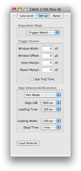
Loads a set of defaults that should work
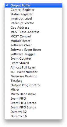
The card’s register list. the current operation will be applied to he selected register. See the documentation that came with the card for more information on each register
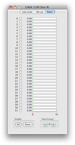
Just displays the rates