CAEN V830

Force a trigger

The counters’ values can be read “on the fly” from VME without interfering on data acquisition process. The model V830 is equipped with a 32 kwords multievent buffer (MEB) memory which may be used to store and readout accumulated data during subsequent counting.
The TRIGGER signal can be provided by an external NIM/ECL signal or by a VME request. It’s also possible to generate a periodical trigger signal by means of an internal programmable timer.
Please refer to the v830.pdf for more details.
There are two types of records produced by this object, a polled read of the counters, and triggered events.
Polled Counter Record format
xxxx xxxx xxxx xxxx xxxx xxxx xxxx xxxx
^^^^ ^^^^ ^^^^ ^^----------------------- V830 ID (from header)
-----------------^^ ^^^^ ^^^^ ^^^^ ^^^^- length (always 20 longs)
xxxx xxxx xxxx xxxx xxxx xxxx xxxx xxxx
--------^-^^^--------------------------- Crate number
-------------^-^^^^--------------------- Card number
xxxx xxxx xxxx xxxx xxxx xxxx xxxx xxxx enabled mask
xxxx xxxx xxxx xxxx xxxx xxxx xxxx xxxx UT time of last read
xxxx xxxx xxxx xxxx xxxx xxxx xxxx xxxx counter 0
..
..
xxxx xxxx xxxx xxxx xxxx xxxx xxxx xxxx counter 31
Triggered Event Record format
xxxx xxxx xxxx xxxx xxxx xxxx xxxx xxxx
^^^^ ^^^^ ^^^^ ^^----------------------- V830 ID (from header)
-----------------^^ ^^^^ ^^^^ ^^^^ ^^^^- length (variable)
xxxx xxxx xxxx xxxx xxxx xxxx xxxx xxxx
--------^-^^^--------------------------- Crate number
-------------^-^^^^--------------------- Card number
xxxx xxxx xxxx xxxx xxxx xxxx xxxx xxxx Channel 0 roll over count
xxxx xxxx xxxx xxxx xxxx xxxx xxxx xxxx
-------------------------------------^^- Acq Mode. 0=disabled,1=Random, 2=periodic
------------------------------------^---- Data Format 0=32Bit,1=24Bit
-----------------------------------^----- Header Enabled (always set)
xxxx xxxx xxxx xxxx xxxx xxxx xxxx xxxx Enabled Mask
xxxx xxxx xxxx xxxx xxxx xxxx xxxx xxxx counter 0 or header (if header, then chan0 follows)
..
..
xxxx xxxx xxxx xxxx xxxx xxxx xxxx xxxx counter 31
Note that only enabled channels are included so list may be shorter than 32 counter values. Also note that the header may or may not be included based on the ‘Include Header’ option.

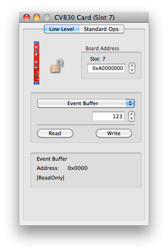
Set the VME Address


The write value to use


Operation to do on the selected register using the current set of values
Extra Info about the selected register
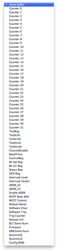
The card’s register list. the current operation will be applied to he selected register. See the documentation that came with the card for more information on each register
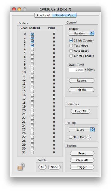

Trigger mode can be ‘Disabled’, ‘Random’, or ‘Periodic”. Periodic uses the Dwell time for an internal trigger generation.

Set to 32 or 24 bit format

Reset counters after trigger.

Clear buffer on front panel clear signal

Period of internal trigger -- use with the ‘Periodic’ trigger mode

Load dialog settings to HW

Read and print counters to status log


Resets most regs -- see manual for exceptions

Ship counter values after a poll -if- run in progress
Resets counters, temp buffers, MEB, registers, etc
