iSeg VHS4030 HV

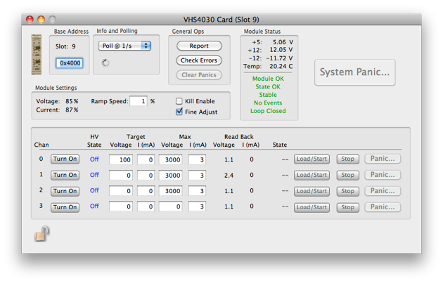


Set the polling rate. Note that if the polling is turned off,the information in the dialog may be invalid.

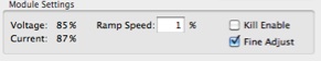
Voltage and Max Current settings

The maximum output voltage is defined through the position fo the potentiometer Vmax. The maximum output current for the channels is defined through the position of the potentiometer Imax. The output voltage and current will be limited to the setting value (if Kill Enable is not enabled) or will be shut off (if Kill Enable is active) after it exceeds the threshold.
For more information, see the manual.


The HV state. See the various states that can appear here and their meanings below.

The rate at which to ramp the voltage up or down as % of max voltage

Stop ramping the voltage by loading in the last voltage read back

Load all settings to card. This may ramp the voltage to a new value if the set and act voltages differ

Panic a channel to zero volts

Actual Voltage and Current as read back from card
Possible HV State Values

Turn on/off each channel

Panic all channels to zero volts

The value of the pots on the front panel setting the max voltage and current as a percent of the units abs max values

If checked, the module will immediately turn off all channels if max voltage or current is are exceeded

If checked, the module will adjust the voltage for temperature drifts
If a panic occurs, the panic condition has to be manually cleared with the ‘Clear Panics’ button
Ramping | I/O | Panic | Ext Inhib | I Trip | V Limit | I Limit | V Bounds | I Bounds | CV | CC
-
• Ramping: A ramp is in progress
-
• I/O: There was an invalid value sent to the unit
-
• Panic: There was an emergency ramp down
-
• I Trip: Kill enabled and the voltage or current limit was exceeded
-
• Ext Inhib: The external inhibit was asserted
-
• V Limit: The hardware voltage limit was exceeded
-
• I Limit: The hardware current limit was exceeded
-
• V Bounds: Voltage was out of bounds. i.e. higher than the front panel pot setting
-
• I Bounds: Current was out of bounds. i.e. higher than the front panel pot setting
-
• CV: Unit under voltage control
-
• CC: Unit under current control
Data Formats
A data record will be shipped during a run if the unit’s values change. The record format is:
xxxx xxxx xxxx xxxx xxxx xxxx xxxx xxxx
^^^^ ^^^^ ^^^^ ^^-----------------------data id
^^ ^^^^ ^^^^ ^^^^ ^^^^-length in longs
xxxx xxxx xxxx xxxx xxxx xxxx xxxx xxxx
^^^^ ^^^^ ^^^^- device id
xxxx xxxx xxxx xxxx xxxx xxxx xxxx xxxx time in seconds since Jan 1, 1970
xxxx xxxx xxxx xxxx xxxx xxxx xxxx xxxx Channel Status Word for channel 0
xxxx xxxx xxxx xxxx xxxx xxxx xxxx xxxx Channel Event Status for channel 0
xxxx xxxx xxxx xxxx xxxx xxxx xxxx xxxx actual Voltage chan 0 encoded as a float
xxxx xxxx xxxx xxxx xxxx xxxx xxxx xxxx actual Current chan 0 encoded as a float
...The last four words above are repeated for channels 1,2, and 3.